55MHz Scope Sensitivity Amplifier
Scope sensitivity amplifier is a vital front-end signal processing for every scope instruments. The function of this circuitry is simple: […]
Read moreFree Simple Circuit Diagram
Scope sensitivity amplifier is a vital front-end signal processing for every scope instruments. The function of this circuitry is simple: […]
Read more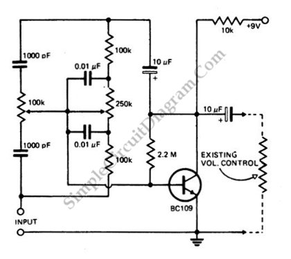
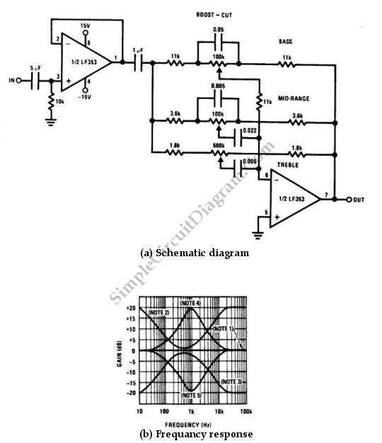
Using active circuit for tone control means that we can provide cut and boost, maintaining overall amplifying factor of original […]
Read more
A signal averager circuit can be formed by an amplifier and active signal rectifier, which is implemented using two operational […]
Read more
A LM3900 quad operational amplifier can be used to build a pulse width (PWM) controller. The LM3900 was chosen because […]
Read more
When you design a circuit with only a single-cell battery, you will need boost-converter to provide enough voltage for most […]
Read more