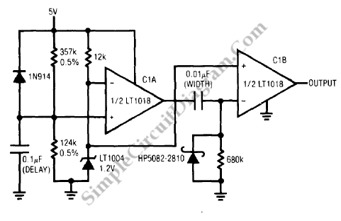
Power-On-Reset Generator
After supply turn-on, another power related requirement involves generating a system reset pulse. The 5V rail comes up when supply power is applied to figure below.

The LT1004 clamps at 1.2V and C1A’s positive input (Trace B) ramps at a time constant determined by the 0.5% resistors and the 0.1 uF capacitor. The output goes high when C1A’s positive input ramps beyond the LT1004 potential, delivering a differentiated pulse to C1B’s negative inputn (Trace C). C1B’s output (Trace D) goes low for a period determined by the 0.01 uF-680k differentiator. This pulse is used for system reset. Quick reset for the 0.1uF delay capacitor given by the 1N914 and the Schottky diode clip’s differentiator caused negative voltages at C1B’s input. The ratio of the 0.5% resistors set the turn-on threshold, in this case 4.8V. 0.1uF unit controlls the output pulse delay, which may be varied. Similarly, output pulse width is set by the RC combination at C1B and may be varied. Spurious output during supply power-up is prevented by the LT1018’s 1.2V minimum supply voltages. [Circuit’s schematic diagram source: Linear Technology Application Note]