Free Simple Circuit Diagram

Higher Input Or Output for L200 Voltage Regulator


This is higher input or output for L200 voltage regulator circuit. This circuit is designed to solve the problem that occurs when the input or output voltages are higher than the device can produce. This circuit uses the external components. Here is the circuit :

Higher Input Or Output for L200 Voltage Regulator

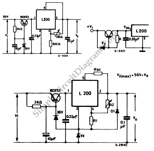
The transistor is used to absorb the excess voltage when there are high input voltage. The SOA of the preregulation transistor and the dissipated power should be calculated. The maximum input volage that can be reached if we use BDX53 is 56 V, so the Vce on transistor is 20V with load current o 2A the operation point remains inside SOA. The ripple at the input of the circuit is reduced by preregulation, so it can recieve an output voltage with negligible ripple.

When we need a high output voltage, we can use a second zener, Vz, that is used to refer an IC’s ground pin to a potential other than zero. To protect the output from short circuit, this circuit uses diode D1. [Source: STMicroelectronics Application Note]

Possibly Related Circuits

  • Digital Voltage Selection Control for L200 Regulator
    This is digital voltage selection control circuit. This circuit uses L200 Regulator. It can be used to regulated the output voltage digitally. Here is the circuit : A combination of P2, R3, R2, and R1 with R5 form voltage divider that determine the output voltage.  The transistor is used to...
  • Wide Input-Voltage Range High-Power LED Driver
    This is a wide input-voltage range high-power LED driver circuit. This circuit based on a buck/boost converter controller regulates current to a white LED. This circuit can be used to replace incandescent bulbs, it efficiently match the LEDs to available power sources such as electrical systems car, batteries, etc. It...
  • Programmable Current and Voltage Regulator for Battery Charger
    This is a programmable current and voltage regulator circuit. It consist of a voltage regulator with external current limitation. The variable resistor R2 is forced by a constant current because of the fixed voltage of 2.77 V at the terminals of R1. The voltage at pin 2 and the output...
  • L200 Light Controller
    This is a circuit of L200 light controller. The output of this circuit is controlled by the surrounding environment’s brightness.  If the brightness increases, the output voltage will increases as well. Here is the circuit : The R1 and photoresistor are connected in parallel. They are used as regulator.  If...
  • L6208 Stepper Motor Controller
    This circuit is a L6208 stepper motor controller. To build this circuit, we can implement slow decay. It allows  lower ripple, lower power dissipation and avoids voltages below GND at output pins during recirculation. Here is the circuit : Using component values on the schematic diagram of the circuit, the...

Search Terms:

variable power supply l200, l200 ic, regulator ic l200, l200 efficiency -saturn -mitsubishi -jbl regulator, l200 voltage regulator, l200 voltage regulator schematics, mitsubishi l200 voltage regulator diagram, l200c, 56v dc regulator circuit diagrams, l200c voltage regulator


Comments are closed.