Op-Amp Application: Non-Inverting Amplifier

This is a high input impedance non-inverting circuit. This circuit provides a closed loop gain equal to (R1+R2)/R1. The close-loop 3 dB bandwidth of this circuit equal to the amplifier unity-gain frequency divided by the closed-loop gain. Here is the circuit :

Op Amp Application Non inverting amplifier circuit schematic diagram

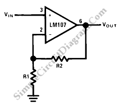
This circuit is different from an inverting circuit. The input impedance of this circuit is very high and equal to the differential input impedance multiplied by loop gain. In this circuit, the output is not inverted. The input impedance is not as important as the voltage and input current, if we uses the circuit in DC coupled applications.

When the input is allowed to float, the outputĀ  of amplifier will go into saturation. It should be noticed when the amplifier must be switched from source to source. [Source: National Semiconductor Application Note]

This entry was posted in Audio and Music and tagged . Bookmark the permalink.,

Possibly Related to "Op-Amp Application: Non-Inverting Amplifier" Circuits

  • Op-Amp Application: Inverting Amplifier
    The figure below show an operational amplifier circuit. Closed-loop gain given by this circuit is R2/R1 when this ratio is small compared with the amplifier open-loop gain, and it’s called as inverting circuit. The value of input impedance is equal … Continue reading →...
  • Op-Amp Application: Unity Gain Buffer
    This circuit is an Unity Gain Buffer. This circuit has a highest input impedance of any OP-AMP circuit. This circuit has a less gain error that is equal to common mode rejection or the reciprocal of the amplifier open-loop gain. … Continue reading →...
  • Op-Amp Circuit: Difference Amplifier
    This is a circuit of difference amplifier. This circuit is an inverting amplifier that allows the subtraction of two voltages and that is the summing amplifier’s complement.This circuit also allows the the cancellation of a signal common to the two … Continue reading →...
  • Op-Amp Application: Level Shifting Amplifier
    Sometimes, in linear equipment design, it’s necessary to take a voltage which is referred to some dc level and generate an amplified output which is referred to ground. Using a differential amplifier similar to that shown in the circuit diagram … Continue reading →...
  • Op-Amp Circuit: Summing Amplifier
    This is a summing amplifier circuit. This is an inverting circuit that provides an inverted output equal to the sum of all three input. This circuit has some advantages such as there is no interaction between the operation and inputs, … Continue reading →...

Comments are closed.