Op-Amp Circuit: Differentiator

This is a differentiator circuit. This circuit can be used to do differential operation. There are two differentiator, the are true differentiator and practical differentiator. The true differentiator is extremely susceptible to high frequency noise due to the increasing AC gain at the rate of 6 dB per octave. Here is the circuit of true differentiator, practical differentiator and Differentiator Frequency Response :

Op Amp Circuit Differentiator circuit schematic diagram
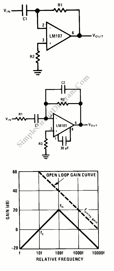
The practical differentiator uses additional components, C2 and R1 to correct the noise problems and stability problems. To reduce amplifier noise and the effect of high frequency input, R1C1 form a 6 dB per octave roll-off network in the input network and a 6 dB per octave high frequency roll-off in the feedback network also formed by R2 and C2.

R1C1 is a RC low pass filter that contributes 90° phase shift to the loop. If we use just R1C1, it may cause stability problems so we can add the R2C2. R1C1 and R2C2 give 90° phase lead to compensate the 90°phase lag of R2C1 and prevent loop instability. [Source: National Semiconductor Application Note]

This entry was posted in Signal Processing and tagged . Bookmark the permalink.,

Possibly Related to "Op-Amp Circuit: Differentiator" Circuits

  • Sine Wave Oscillator
    This is a Sine Wave Oscillator circuit. This circuit as known as  amplitude-stabilized sine-wave oscillator. It can gives high purity sine-wave output down to low frequencies with minimum circuit complexity. This circuit has a several advantages such as it does … Continue reading →...
  • Op-Amp Application: Inverting Amplifier
    The figure below show an operational amplifier circuit. Closed-loop gain given by this circuit is R2/R1 when this ratio is small compared with the amplifier open-loop gain, and it’s called as inverting circuit. The value of input impedance is equal … Continue reading →...
  • Philip’s Dynamic Noise Limiter
    When there is quiet passages, a tape noise becomes disturb. This noise can be reduces using Philips’ Dynamic Noise Limiter circuit. The principle operation of this circuit is improve the signal-to-noise ratio during the quite periods by decreasing the gain … Continue reading →...
  • High-Q Notch Filter with Active Twin T Network
    This is a circuit of High-Q Notch Filter. This circuit consist of LM102 and a twin “T” network. Twin T network sum two signal from different path with different phase shift. At certain frequency, the phase shift will be 180 … Continue reading →...
  • Quadrature Sinewave Oscillator
    Quadrature oscillator is another type of phase shift oscillator. This circuit produce two sine wave signal. One of them is shifted 90 degree from the other signal. The output that shifted 90 degree is called cosine signal and the other … Continue reading →...

Comments are closed.