Low-, Band-, and High-Pass Single Supply Multiple Feedback Filter

This is Low-, Band-, and High-Pass Single Supply Multiple Feedback Filter circuit. This circuit uses MFB topology, which has some advantages and disadvantages. The advantages of MFB topology are low cost, easy to implement and very versatile. The disadvantage of MFB topology is it has complex calculation. This circuit uses a unity gain Butterworth, so the circuit will give a close approximation.  Here is the circuit:
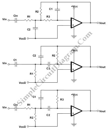
Low Band and High Pass Single Supply Multiple Feedback Filter circuit schematic diagram

LOW PASS:

unity gain Butterworth

R1 = R2 = R/squareroot(2)

R3 = R/(2*squareroot(2) )

C1 = C

C2 = 4C

Fo = 1/(2pi RC)

HIGH PASS

Unity Gain Butterworth

Fo = 1/(2 piRC)

C1 = C2 = C3 = C

R1 = 0.47R

R2 = 2.1R

BAND PASS

Gain = 2.3 dB

R3 = 100R

R2 = 0.001R

R1 = 10R

C2 = C

C1 = 10C

Fo = 1/(2.32 piRC)

[Source: Texas Instruments Application Note]

This entry was posted in Signal Processing and tagged . Bookmark the permalink.,

Possibly Related to "Low-, Band-, and High-Pass Single Supply Multiple Feedback Filter" Circuits

  • Low- and High-Pass Single Supply Sallen-Key Filter
    This is a circuit of Low- and High-Pass Single Supply Sallen-Key Filter. This circuit uses popular second-order topologies, the Sallen-Key topology, because it has some advantages such as just need one a single op amp and four passive components, and … Continue reading →...
  • Single Op-Amp Twin-T Band-Pass and Notch Filter
    This is a Single Op-Amp Twin-T Band-Pass and Notch Filter circuit. This circuit uses the twin-T topology which requires one or two op amps and three resistors and three capacitors. That’s mean this topology based on a passive (RC) topology. … Continue reading →...
  • Low-Pass and High-Pass RC Filter Frequency Calculator
    This is a simple Low-Pass and High-Pass RC Filter Frequency Calculator. This calculator is used to calculate the corner frequency of low pass and high pass filter. To change from low pass to high pass, just switch the position of … Continue reading →...
  • 20Hz High-Pass Rumble Filter, Subsonic Blocker
    This is a schematic diagram of 20-Hz high-pass rumble filter circuit.  Rumble noise could come from many sources, such as wind blow around an outdoor microphone, mechanical disturbance on phonograph, or many other possibilities. We can remove this noise by … Continue reading →...
  • A 20-kHz, Third-Order Low-Pass Filter
    This is a third order low pass filter that has corner frequency of 20kHz. It is twice as high as the auto-zero clock frequency. Here is the circuit : The input signal operation is allowed to across its entire gain … Continue reading →...

Comments are closed.