TMP01 Celsius Scale Temperature Sensor
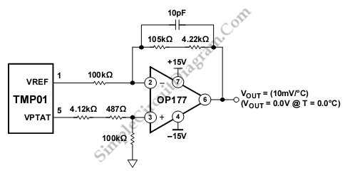
The schematic diagram described here is a TMP01 Celsius Scale Temperature Sensor circuit. This circuit is used to convert the VPTAT output voltage that is calibrated in Kelvins into an output in degrees Celsius on a voltmeter display. This circuit uses an amplifier that is configured as a differential amplifier. Here is the schematic diagram of the circuit:

The VREF voltage exactly cancels the VPTAT voltage at 0.0°C due to the scaled resistors. This circuit convert 5 mV/K into 10 mV/°C because the gain from VPTAT to the output is two. If output voltage is 800 mV, the temperature is 80°C. the inaccuracies of the resistor values causes Circuit errors. The errors can be reduced tp less then 10mV, or 1°C using 1% resistors. To ensure against oscillations, this circuit uses The 10 pF feedback capacitor. potentiometer can be added in series with either 100K resistor to give better accuracy. [Circuit’s schematic diagram source: analog.com]