Analog “Watchdog” Timer
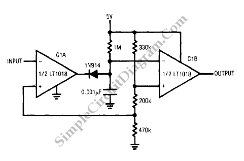
The circuit on the following figure is not for power supply management, but serves to prevent lock-up in processor based systems. If the system misses an instruction due to transient hardware or software events, this could be occur. A predictable cessation of pulse events somewhere in the system is caused by such a processor hang-up. This circuit issues a reset command in response to such a cessation.

A pulse train appears at the circuit input in normal operation, causing C1A’s output (Trace B) to pulse low. Each time C1A’s output goes low, the diode path discharges the 0.01uF capacitor (Trace C). Interruption of the input pulse train (after the 7th vertical division) lets the capacitor to charge beyond C1B’s threshold, triggering it low. We can use this pulse to reset the system. To accommodate various input pulse train repetition rates, C1B’s negative input RC values may be adjusted. [Circuit’s schematic diagram source: Linear Technology Application Note]