RS-485 Signal Loss Detection
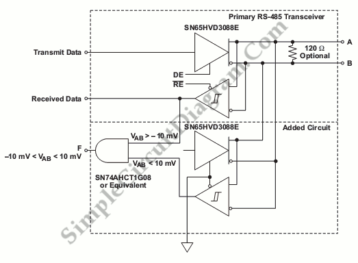
The safety shutdown and fault isolation protocol are critical in many telecommunication, industrial, data processing system and industrial. To share data between communication processor or single-board computers, actuator and sensors, the fault detection system uses RS-485. This RS-485 uses two signal wires to detection of valid signal levels that require a differential window comparator and to transmit data. Here is the schematic diagram of different window comparator :

This circuit constructed with an AND gate and two SN65HVD3088E RS-485 transceivers. The voltage between the inverting and non-inverting RS-485 signals below which bus state is low and above which the bus state is high. The differential input voltage threshold of the SN65HVD3088E is between -200mV and -10 mV and the different input voltage threshold of standard receivers is between 200mV and -200mV.
This circuit uses two SN65HVD3088E, first SN65HVD3088E is used to determine if the differential input voltage is above –10 mV or less than –200 mV, and the second SN65HVD3088E is used to determine if the differential input voltage is above 200 mV or below 10 mV. If the differential input voltage, VAB, is greater tah -10mV, the output of upper receiver is true (high) and if VAB is smaller than 10 mV, the lower-receiver output is true (high). Both outputs are used as input gates A to detect the fault. [Source: Texas Instruments Analog Application Journal]