PWM Modulator Using Op-Amp
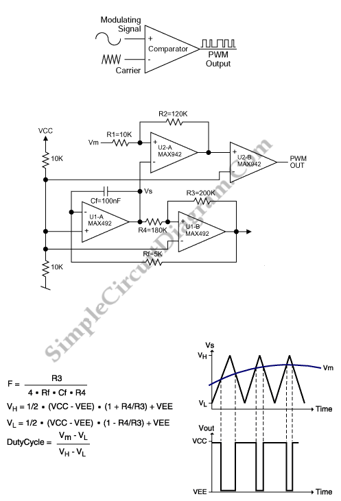
This is a simple PWM modulator circuit. Comparing the message signal to a ramp or triangular waveform is the simplest way to produce a PWM signal. When the input is greater than the triangular waveform (the carrier), the resulting output is high, when the input is less than triangular waveform, the output is low. So, a comparator and triangular-waveform generator are required. Here is the circuit :

The triangular wave is generated by a MAX492 dual rail-to-rail op amp. The triangular waveform’s dynamic range must be larger than that of the sensor, so we need rail-to-rail capability. Cf and Rf determine the slope of the positive- or negative-going ramp that is produced by the integrator circuit (U1-A). To reverse the slope of the ramp, and the triangular-waveform frequency, this circuit use the comparator stage (U1-B). Following equation shows the triangular-waveform frequency :
F=R3/(4*Rf*Cf*R4)
Using component values shown in the figure, the ramp frequency and thus the PWM output is about 500Hz. The sensor’s analog voltage and the ramp waveform are compared by a dual comparator (MAX942). The accuracy for the PWM output in the presence of rapidly changing sensor inputs is insured by R2 and R1 by providing hysteresis. U2-B provides additional buffering and isolation, the PWM output is provided by U2-A. [Source: maxim-ic.com]