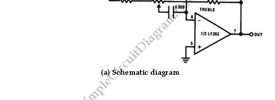
Free Simple Circuit Diagram

Posts Tagged ‘Filter’


6 Band Graphic Equalizer

The circuit diagram below shows a circuit of graphic equalizer 6 band of regulation. The potentiometer RV1-6 regulates each band, and the sliding type is the recommended for better visual indication. . The gain is null (flat) in the center position of potentiometer, but in the maximum and minimum position has +/- 15 dB, boost …

Read More

3 Band Graphic Equalizer

Below is a classic circuit of regulation of tone of three way. With this circuit, we can regulate low, mid and high frequencies of acoustic signal. We can regulate the boost/cut in the range of +- 18 dB/oct.

The supply on the the circuit is 15V, but it can be supplied with 9 until 30V. It’s …

Read More

Voltage-Controlled Tone/Volume/Balance Circuit

The LM1036 is a DC controlled tone (bass/treble), volume and balance circuit which can be applied in car radio, TV and audio systems. Loudness compensation to be simply effected is allowed by an additional control input.

Control of the bass, treble, balance and volume function are provided by four control inputs through application of DC voltages …

Read More

Single Op-Amp Twin-T Band-Pass and Notch Filter

This is a Single Op-Amp Twin-T Band-Pass and Notch Filter circuit. This circuit uses the twin-T topology which requires one or two op amps and three resistors and three capacitors. That’s mean this topology based on a passive (RC) topology. It is not difficult to match the six passive components, but it is critical. we …

Read More

Low- and High-Pass Single Supply Sallen-Key Filter

This is a circuit of Low- and High-Pass Single Supply Sallen-Key Filter. This circuit uses popular second-order topologies, the Sallen-Key topology, because it has some advantages such as just need one a single op amp and four passive components, and it is cheap topology. Besides that, this topology is very easy to tune the frequency. …

Read More

Low-, Band-, and High-Pass Single Supply Multiple Feedback Filter

This is Low-, Band-, and High-Pass Single Supply Multiple Feedback Filter circuit. This circuit uses MFB topology, which has some advantages and disadvantages. The advantages of MFB topology are low cost, easy to implement and very versatile. The disadvantage of MFB topology is it has complex calculation. This circuit uses a unity gain Butterworth, so …

Read More