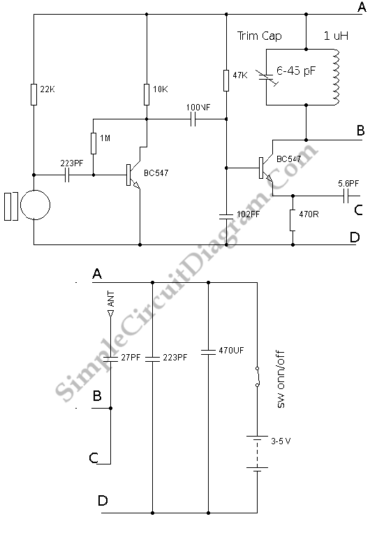
Two Transistors FM Transmitter
Basically, this circuit is a radio frequency (RF) oscillator that operates around 100 MHz. The audio which is picked up and amplified by the electret microphone is fed into the audio amplifier stage built around the first transistor. Output from the collector is fed into the base of the second transistor. By varying the junction capacitance of the transistor, this will modulate the resonant frequency of the tank circuit (the 5 turn coil and the trimcap). Junction capacitance is a function of the potential difference applied to the base of the transistor. The tank circuit is connect to a Colpitts oscillator circuit.

To calibrate this circuit, put the transmitter about 10 feet from a FM radio. The radio frequency is set somewhere about 89-90 MHz, then walk back to the Fm Tx and turn it on. The winding of the coil is spread apart by approximately 1mm from each other. No coil winding should be touching another winding. To tune the trim cap, use a small screw diver. After every adjustment remove the screwdriver from the trim screw so the LC circuit is not affected by stray capacitance. We also can use a plastic screwdriver. Have a second person tune up and down the FM dial after every adjustment if you have difficulty finding the transmitting frequency. One full turn of the trim cap will cover its full range of capacitance from 6pF to 45pF. About one tenth of the full range of the tuning cap is the normal FM band tunes in over. To adjust it in steps of 5 to 10 degrees at each turn is the best time. To tuning this is not difficult but we have to takes a little patience. The Tx emits harmonics, that’s the reason why there must be at least 10 ft. separation between the radio and the Tx. It does not only emit on one frequency but on several different frequencies close to each other.