Voltage to Frequency Converter Using UJT

The following voltage to frequency converter (V/FC – VCO) circuit consist of a UJT (uni-junction transistor) oscillator in which the timing charge capacitor C2 is linearly depends on the input signal voltage. The voltage across resistor R5 set the charging current, which is accurately controlled by the amplifier. Here is the schematic diagram of the circuit:

Read more
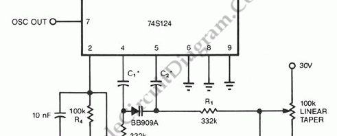
74S124 High Frequency VCO with Varactor

The following schematic diagram shown a conventional which is modified to become a VCO (voltage-controlled oscillator) circuit. By replacing the conventional fixed capacitor with a variable capacitance diode (varactor), we can turn a 74S124 multivibrator into a wide-band VCO. High speed logic 74S series is used here to enable this circuit for high frequency operation. Here is the schematic diagram […]

Read more

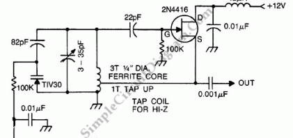
Voltage Controlled Oscillator for Commercial FM Band

VCO (voltage controlled oscillator) is an electronic signal generator which produce a signal that has variable frequency depends on a voltage level at its control input. Many VCO circuits are based on ramp generator to produce a variable frequency output, but they produce a square wave signal. With varactor (voltage controlled variable capacitor), we can produce a high quality sine […]

Read more

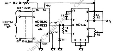
Digitally Programmable Oscillator

The schematic diagram below shows a digitally programmable oscillator circuit. This programmable oscillator circuit is based on V/F (voltage to frequency) converter, which is programmable by an analog voltage at the input. To make it digitally programmable, a DAC (digital to analog converter) is added to feed the V/F input. The components of the DAC is AD7520 multiplying D/A converter […]

Read more
1 2 3