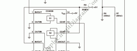
Voltage To Frequency Converter
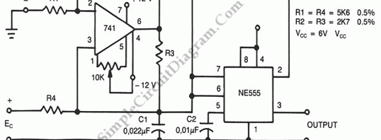
Using this circuit, we can accept positive or negative or differential control voltages. When the control voltage is zero, the output frequency is zero. To charge the timing capacitor C1 linearly, the 741 op amp forms a current source controlled by the voltage EC. The capacitor charges and discharges between 1/3 Vcc and 2/3 Vcc because NE555 is connected in […]

Read more
Voltage-To-Frequency Converter (VFC) with 555 IC

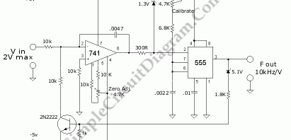
Voltage-to-frequency converter (VFC)  circuit is shown in the schematic diagram below. The circuit employs 555 IC as the core of its function. This circuit uses +5V and -5V supply voltages, and the input is limited to 0-2V. You can adjust the zero point by grounding the input and adjust the 4k7 pot to obtain the lowest frequency oscillation. [Circuit’s schematic […]

Read more

Micropower VCO (Voltage-Controlled Oscillator)

This is a schematic diagram of a micropower voltage-controlled oscillator circuit. This circuit can generate square and triangle wave outputs and only need 50µA from a single 5 V supply. This circuit consist of combination of an  inexpensive quad CMOS switch and two OP90s. Here is schematic diagram of the  the circuit : The integrator in this circuit is A1. […]

Read more
1 2 3