Micropower VCO (Voltage-Controlled Oscillator)
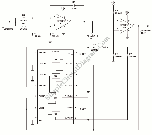
This is a schematic diagram of a micropower voltage-controlled oscillator circuit. This circuit can generate square and triangle wave outputs and only need 50µA from a single 5 V supply. This circuit consist of combination of an inexpensive quad CMOS switch and two OP90s. Here is schematic diagram of the the circuit :

The integrator in this circuit is A1. The charging current is switched to yield negative and positive ramps symmetrically by S1. A2 acts as Schmitt trigger with a precise hysteresis of 1.67 V and set by R6, R7, R5 and associated CMOS switches. A2 bounds the integrator. The resulting output of A1 is a triangular wave with lower and upper levels of 1.67V and 3.33V. The frequency of this circuit is determined by following equation:
fout=Vcontrol(V) x 10 Hz/V
The frequency can be changed easily by varying C1. This circuit can operate well up to a few hundred hertz. [Circuit’s schematic diagram source: Analog Application Note]