PLL FM Demodulator
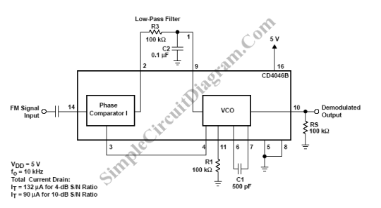
PLL (Phase Locked Loop) can be used to make a FM demodulator. PLL circuit track the input frequency by controlling a voltage input of a VCO (Voltage-Controlled Oscillator). Since the VCO is controlled to follow the input frequency, then the controlling signal is directly proportional to the modulating signal. Here is the schematic diagram of the cicuit:

For this example, an FM signal consisting of a 10-kHz carrier frequency was modulated by a 400-Hz audio signal. The schematic diagram shows the connections of the CD4046B as an FM demodulator. The total FM signal amplitude is 500 mV, therefore, the signal must be ac coupled to the signal input (terminal 14). [Schematic diagram source: Texas Instruments Application Report]