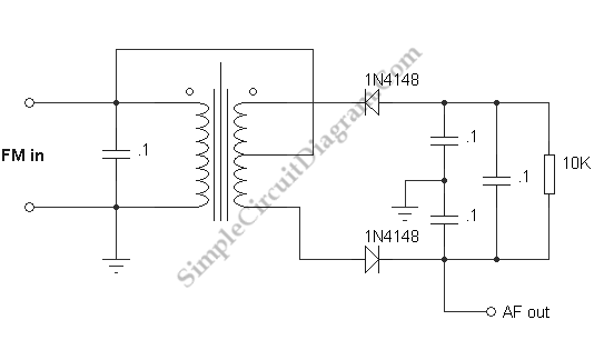
Ratio Detector for FM Demodulation
This view is not far from wrong because the operation of FM detectors is widely regarded as mysterious. The ratio detector to find out how it works, without going deeply into the theory at this point, or studying other forms of FM detector that are also used, and somewhat similar are covered here. To give an output voltage that is proportional to the deviation from the center frequency is necessary, a much more difficult job than AM detection, and one that cannot be performed by a simpler mixer.
Below is a circuit demonstrating ratio detection. It’s not recommended as a practical demodulator, since the primary inductance was only about 0.8 uH, requiring a capacitor as large as 0.1 uF to resonate it at some frequency less than 1 MHz, the transformer (in particular) seems ill-suited to the purpose. Your modulator will probably work much better if you can find a transformer with a higher primary inductance. Choose the capacitor which have resonant frequency around 500 kHz, which is convenient for us. Since the primary would have a DC bias, the lead to the center of the secondary would have a blocking capacitor in it in a normal receiver circuit.

Below will be explained about how the circuit work. The signal that goes directly to the center tap of the secondary splits equally there, and the diode rectify it to create equal voltages across the two capacitors to ground, in a kind of voltage doubler action. Then, the signal is applied to the tuned circuit. The diodes are also equally affected when it is exactly on the resonant frequency, and the capacitor on the right is charged by the equivalent half-wave rectifying action. The voltage across this capacitor and the sum of the voltages across the two capacitor to ground is equal. A phase shift is produced that is either capacitive or inductive, depending on the direction of the deviation,which is increases the current through one diode while decreasing it in the other (by vector addition of the currents) when the frequency varies from resonance. The total voltage across the two capacitor to ground remains constant. The voltage is constrained by the capacitor at the right, while one increases and the other decreases proportionally to the frequency deviation. You will find that the ratio detector is not sensitive to the level, on of its advantages, if you remove the modulation and vary the amplitude of the signal. The signal has to be limited before detection because some FM demodulators respond to the amplitude as well as the frequency. For a ratio detector, this is not necessary.