Colpitts Crystal Oscillator
We can create Crystal Colpitts oscillator using a parallel mode crystal and a transistor. The circuit shown by the following figure
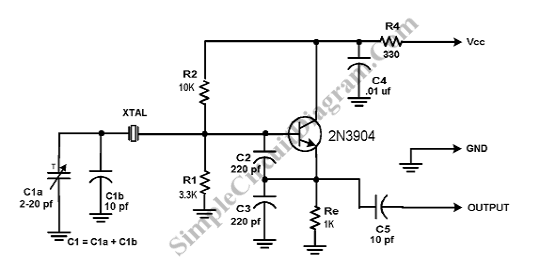
As an inductance, this circuit uses crystal. The crystal circuit consist of a large value capacitive divider that is used between gate, a small series capacitor, ground, and source. Component’s values that we choose must produce a highest ratio between C2+C3 and C1. Usually the ratio is 5 to 10 to 1. The schematic shows the typical values. There is a little loading on the crystal. Variations in device characteristics causes drift and the relatively high values of C2 and C3 “swamp out” variations. C1 is used to tune the frequency. A clean enough sine wave appears at the emitter of the transistor.