RS-485 Signal Loss Detection

The safety shutdown and fault isolation protocol are critical in many telecommunication, industrial, data processing system and industrial. To share data between communication processor or single-board computers, actuator and sensors, the fault detection system uses RS-485. This RS-485 uses two signal wires to detection of valid signal levels that require a differential window comparator and to transmit data. Here is the schematic diagram of  different window comparator :

RS 485 Signal Loss Detection circuit schematic diagram

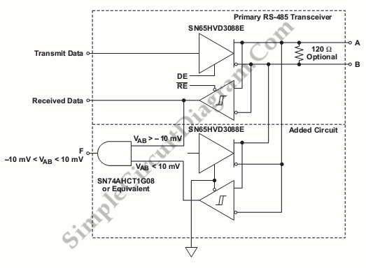
This circuit constructed with an AND gate and two SN65HVD3088E RS-485 transceivers. The voltage between the inverting and non-inverting RS-485 signals below which bus state is low and above which the bus state is high. The differential input voltage threshold of the SN65HVD3088E is between -200mV and -10 mV and the different input voltage threshold of standard receivers is between 200mV and -200mV.

This circuit uses two SN65HVD3088E, first SN65HVD3088E is used to determine  if the differential input voltage is above –10 mV or less than –200 mV, and the second SN65HVD3088E is used to determine if the differential input voltage is above 200 mV or below 10 mV. If the differential input voltage, VAB, is greater tah -10mV, the output of upper receiver is true (high) and if VAB is smaller than 10 mV, the lower-receiver output is true (high). Both outputs are used as input gates A to detect the fault. [Source: Texas Instruments Analog Application Journal]

This entry was posted in Control Electronics, Test and Measurement and tagged . Bookmark the permalink.,

Possibly Related to "RS-485 Signal Loss Detection" Circuits

  • Power Failure Detection Trigger Memory Saving
    Sometimes the power goes down and we unable to save memory content. When the power goer down, the memory save circuit can be used to save memory content. This is a very useful circuit because the AC line dropout detection … Continue reading →...
  • Split Phase-Data Synchronizer and Decoder
    Waveform A is timing diagram that shows A split-phase data signal. It consist of a series of binary digits that occur at a periodic rate. Duration of each bit and the periodic bit rate is constant but the weight of … Continue reading →...
  • Temperature Under–and Over-Range Sensing with A Window Comparator
    The window can be used to monitor a TEC operating temperature and indicate an out-of-range condition. To indicate an over temperature or under-temperature, this circuit uses the separated outputs. If the output’s logic is HIGH, the condition is over-temperature, if … Continue reading →...
  • Audio Signal Clipping Indicator
    A window comparator formed by two op-amps packaged into IC1 is the heart of the circuit below. With this technique, we can detect precisely and symmetrically either the positive or negative peak value reached by the monitored signal. The op-amps … Continue reading →...
  • Digitizing a LVDT Transducer Interface Output
    Digitizing transducer interface output voltage is shown on circuit diagram below. The transducer in this case is the NE5521, an LVDT (Linear Variable Differential Transformer) Signal Conditioner. To ensure that the input to the A/D does not go excessively beyond … Continue reading →...

Comments are closed.