11th Mar 2010 | Comments Off
To protect downstream circuits from overvoltage conditions that show up during load-dump events or transients, we can use the MAX6495–MAX6499/MAX6397/MAX6398 overvoltage protection (OVP) devices. Here’s the circuit diagram:

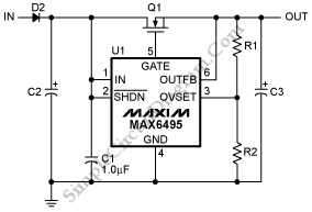
This devices work by controlling an n-channel MOSFET wired in series with the power rail. The gate pulls low and the MOSFET shuts off, disconnecting the power rail when the voltage surpasses overvoltage threshold which is defined by user. [Source: maxim-ic.com]
Possibly Related Circuits
- Discrete Overvoltage Protector for Automotive Application
This is a circuit of discrete overvoltage protector for automotive application. There are two basic thing that must be done by protection circuit. They are prevent voltages greater than the maximum allowable from being applied to the IC pins and the protection circuit not to intrude on the normal function... - Compact Power Factor Controller
This is compact power factor controller circuit. It stabilizes device’s electrical demand to give best power factor characteristic of many types of loads. In many application, a direct rectification of the AC line followed by bulk capacitor filtering is used to get the high DC voltage. This capacitor filtering will... - PMOS FET Following The Output for Soft-Start Mechanism
Using the following PMOS FET switch regulator output, in series with the regulator’s load as shown in the picture below is the most simple method. Switch placement should really be noted. To ensure that the regulator remains stable, the switch should be placed after regulators required minimum output capacitance (ie,... - Motor Speed Control Using PWM
Pulse width modulation or familiarly known as PWM is used to control the delivered power to load without loosing the efficiency. The speed of an electric motor is controlled by controlling the power source of the motor. The simplest method to provide a variable power supply is by providing a... - Wide Input-Voltage Range High-Power LED Driver
This is a wide input-voltage range high-power LED driver circuit. This circuit based on a buck/boost converter controller regulates current to a white LED. This circuit can be used to replace incandescent bulbs, it efficiently match the LEDs to available power sources such as electrical systems car, batteries, etc. It...
Search Terms:
max6495, over voltage limiter, overvoltage limit circuit, overvoltage limiter railway, over voltage circuit diagram, under over voltage circuit diagram, over voltage limiter circuits, over voltage circuits diagram, under and overvoltage circuit diagramCategory: Power Supply
Tags: Circuit Protection, Power Control