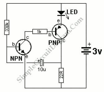
Transistor Tester

We can use this basically a high gain amplifier with feedback circuit to cause the LED flash at rate determined by the 10u and 330k resistor. Before insert the unknown transistor, remove one of the transistor. The LED flash when it’s NPN with pins as shown in the photo. Remove one of the transistors to turn the unit off.
TRANSISTOR TESTER 2 circuit schematic diagram

[Source: Talking Electronics]

This entry was posted in Test and Measurement and tagged . Bookmark the permalink.,

Possibly Related to "Transistor Tester" Circuits

  • Audible Transistor Tester
    All types of transistors including Darlington and power will be tested in this project. Connect the 9v battery around the other way at points A and B to test PNP types. The transformer in the photo is a 10mH choke … Continue reading →...
  • Simple IR Remote Tester
    The most common problem for infra-red (IR) remote control is the failure to transmit the pulsed infra-red light. The circuit shown in the schematic diagram below is an IR remote control handset tester. This device is very useful and easy … Continue reading →...
  • Good/Bad Transistor Tester
    Good/Bad transistor tester means that this instrument can only determine if the transistor is good or bad, nothing more. Any transistor with gain equal to 30 or more will be considered as good by this tester, and otherwise will be … Continue reading →...
  • Transistor Capacitance Meter Circuit
    This is a circuit that can be used to meter the capacitance. This circuit is similar to previous meter circuit. It has a little difference, this circuit uses transistors rather than logic gates. Here is the circuit: This circuit uses … Continue reading →...
  • LED Flasher Using Transistor
    This simple LED flasher circuit will turn ON and OFF two LED alternatively. The first LED will turn ON when the second LED is OFF for some period, then the first led will turn OFF and the second LED will … Continue reading →...

Comments are closed.