Fast Sample-And-Hold
Sample and hold circuit is used to pick a signal and hold the level at its output, making it useful for analog digital conversion or other application where the processing need a constant level signal for the input. The circuit that is shown in the schematic diagram below is one example of fast sample and hold circuit. This sample and hold circuit uses 531 opamp IC. The Q2, Q1 and IC1 receive complete feedback from JFET Q1 which is turned on by the strobe pulse developed from the input of 531. The C1 is used to charge voltage until equal to input signal plus gate-to-source offset voltage of Q2. Here is the schematic diagram of the circuit:
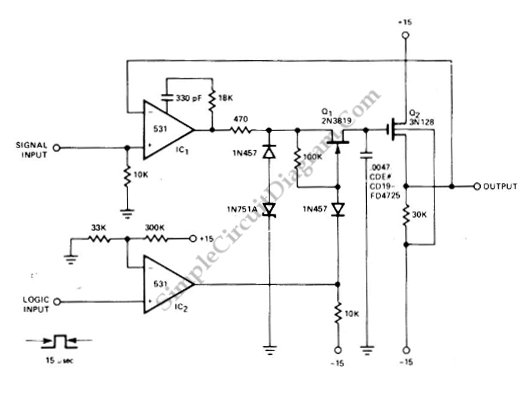
The voltage is held until time of next strobe pulse by C when the feedback loop is broken. An ideal sample and hold circuit will be able to hold the level for infinite period, but this circuit is not an ideal one as this circuit has decay in output voltage between samplings of 1mV/s. [Circuit’s schematic diagram source: Signetics Analog Data Manual]