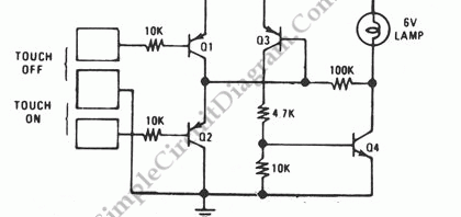
Pulse Width (PWM) Controller Circuit
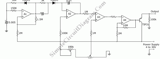
A LM3900 quad operational amplifier can be used to build a pulse width (PWM) controller. The LM3900 was chosen because it only need single supply voltage of 4 to 30 V. This circuit can give 100 percent pulse-width control. A1 op-amp forms a 1 kHz oscillator, generating a square wave oscillator for the basic oscillation. A2 is a ramp generator […]
Read more