Transistor Capacitance Meter Circuit

Sponsored Links

This is a circuit that can be used to meter the capacitance. This circuit is similar to previous meter circuit. It has a little difference, this circuit uses transistors rather than logic gates. Here is the circuit:
transistor capacitance meter circuit circuit schematic diagram
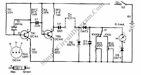
This circuit uses pnp transistor. if we can’t find exact type as shown in the circuit, we can use almost any pnp transistor with collector current handling capability of 100 mA and frequency bandwidth og 100MHz to replace the transistor.

This entry was posted in Test and Measurement and tagged . Bookmark the permalink.

Possibly Related to "Transistor Capacitance Meter Circuit" Circuits

Sponsored Links
  • Capacitance Meter Circuit
    Capacitance meter is one instrument that you should have in your toolbox if you are an electronics hobbyist, or if you’re a professional electronic technician. If you can’t afford to buy such instrument or you you can’t find it on … Continue reading →...
  • Inductance Meter Adapter Circuit, Turns Your Digital Voltmeter to Inductance Meter
    Measuring inductance is important in making your hand-made inductors, especially when you do-it-yourself (DIY) your coil winding. An inductance meter adapter circuit would be helpful since you can measure inductance using your general purpose digital voltmeter (DVM). This circuit cost … Continue reading →...
  • Simple pH Meter Circuit, A Low Cost Adapter for Your Digital Voltmeter
    What is A pH Meter? A pH meter is actually a precise voltmeter  that measures the generated voltage of a pH electrodes. The requirement of such meter is high input impedance and has the gain of  voltage-pH conversion. The standard … Continue reading →...
  • LED Flasher Using Transistor
    This simple LED flasher circuit will turn ON and OFF two LED alternatively. The first LED will turn ON when the second LED is OFF for some period, then the first led will turn OFF and the second LED will … Continue reading →...
  • Pulse Position Modulator Using 555 IC
    Pulse position modulation is similar to pulse width modulation, but the frequency is not constant.  Like pulse width modulator circuit, pulse position modulator can be easily constructed using 555 IC.  Here is the schematic diagram of the circuit: If you … Continue reading →...

Comments are closed.