Coincidence Detector for Logic Signals
This is a coincidence detector circuit. This circuit is very useful for monitoring complex logic circuits. This circuit has two inputs, A and B. if A and B are both low, red LED will be on, and green will be on when A and B are both high. The indicator will be off when one of input is low and the other is high. Here is the schematic diagram of the circuit:
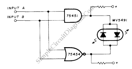
The Monsanto MV5491 dual red/green LED is used as indicator. The red and green LEDs have different voltage requirements, so 100 ohms in lower +5 V lead and 220 ohms in upper lead. SN75454 and SN75451 are used as drivers.