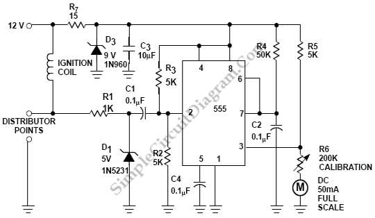
Car Tachometer with 555 IC
Pulses are received by the timer from the distributor points. When the timer output is high, Meter M receives a calibrated current through R6. The meter don’t receives any current for that part of the duty cycle after time-out. A visible indication of engine speed is provided by integration of the variable duty cycle by the meter movement. Here’s the circuit diagram:

[Source: Philips Semiconductors Application Note]