Peak (Pulse) Voltmeter
This is a Peak Voltmeter circuit. This circuit can be viewed as a pulse stretcher, which catch fast pulse signal to be measured by a slow response voltmeter. Even a fast response meter need this circuit since our visual perception won’t be able to catch a fast event. Here is the schematic diagram of the circuit:
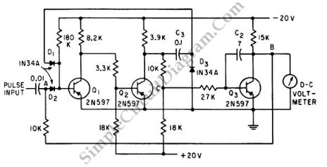
This circuit is used to measure the peak of pulse. This circuit uses flip-flop to compare input pulse with a voltage already on integrating capacitor. The capacitor will be charged to match peak voltage of input. The flip-flop also control the integrator Q2. [Circuit’s schematic diagram source: seekic.com]