Ultrasonic Proximity Detector
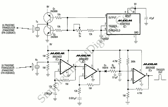
This is ultrasonic proximity detector circuit. This circuit consist of micropower opamp and a pair of matched piezo-ceramic tranducers. It uses a 9V battery as power supply. This circuit uses the radar principle, when the objects or people is nearby it will reflect the transmitter’s steady tone back to the reciever. Here is the circuit :

First circuit is a transmitting transducer, it can draw spikes of current from its signal source. Q1 and Q2 compose a push-pull driver that is used to buffer the timer which is used to prevent damage from these undesirable spikes. For transmit frequency of 40 kHz, we must adjust the potentiometer R1.
The second circuit is the receiver, it must offer high gain at ultrasonic frequencies. To provide low supply and necessary wide bandwidth, this circuit uses op amps IC3 and IC2. The op amp IC4 is used as output-signal comparator and offer a rail-to-rail output swing and extremely low quiescent current. If we want to change the gain, we must adjust the pole/zero positions associated with op amps IC3 and IC2 to maintain stability. [Source: Maxim Application Note]