Op-Amp Application: Unity Gain Buffer

This circuit is an Unity Gain Buffer. This circuit has a highest input impedance of any OP-AMP circuit. This circuit has a less gain error that is equal to common mode rejection or the reciprocal of the amplifier open-loop gain. The multiplication of the open-loop gain and the differential input impedance parallel with common mode input impedance will result the input impedance of this circuit. Here is the circuit:

Op Amp Application Unity Gain Buffer circuit schematic diagram

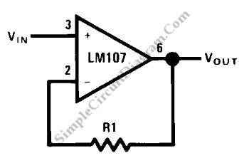
The source resistance gives bias current to the amplifier. The bias current will cause an error at input of the amplifier. The error can be occured because the voltage drop across the source resistance. So, to build this circuit we should choose low bias current amplifier such as LH102.

There are some note that must be concerned in building this circuit, they are when the amplifier common mode range is exceeded some amplifiers exhibit a latch-up mode, the amplifier common mode range may be limit the amplifier output swing, and for unity gain operation, the amplifier must be compensated. [Source: National Semiconductor Application Note]

This entry was posted in Audio and Music and tagged . Bookmark the permalink.,

Possibly Related to "Op-Amp Application: Unity Gain Buffer" Circuits

  • Op-Amp Application: Inverting Amplifier
    The figure below show an operational amplifier circuit. Closed-loop gain given by this circuit is R2/R1 when this ratio is small compared with the amplifier open-loop gain, and it’s called as inverting circuit. The value of input impedance is equal … Continue reading →...
  • Op-Amp Application: Non-Inverting Amplifier
    This is a high input impedance non-inverting circuit. This circuit provides a closed loop gain equal to (R1+R2)/R1. The close-loop 3 dB bandwidth of this circuit equal to the amplifier unity-gain frequency divided by the closed-loop gain. Here is the … Continue reading →...
  • Op-Amp Circuit: Difference Amplifier
    This is a circuit of difference amplifier. This circuit is an inverting amplifier that allows the subtraction of two voltages and that is the summing amplifier’s complement.This circuit also allows the the cancellation of a signal common to the two … Continue reading →...
  • Op-Amp Application: Level Shifting Amplifier
    Sometimes, in linear equipment design, it’s necessary to take a voltage which is referred to some dc level and generate an amplified output which is referred to ground. Using a differential amplifier similar to that shown in the circuit diagram … Continue reading →...
  • High Gain JFET Audio Amplifier
    This is a simple high gain JFET audio amplifier circuit. This circuit need very low power but it provides high gain amplifying function. It also called “JFET ยต amp”. Here is the circuit : The lower drain current is, the … Continue reading →...

Comments are closed.