Turbo Bass (Booster)
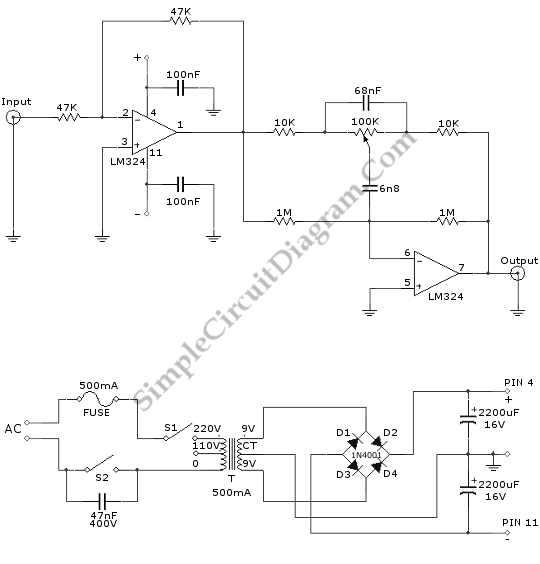
This is a Turbo Bass circuit. Using this circuit, the low frequency sound signals(bass) can be multiplied. This circuit is an active circuit. The first op-amp is used to buffer the audio input signal. The signal will be filtered by the second op-amp which will give bass signal output. Here is the schematic diagram of the circuit:
The overall gain of this bass booster circuit is 1, mean there will be no gain if we set the potentiometer at the center position. This turbo bass circuit can be viewed as 1 band tone control/equalizer. This circuit is recommended for woofer or sub-woofer amplifier, but not for general one since it attenuates the high frequency (treble) part. If you already have a regulated symmetric power supply, you don’t have to build the unregulated one shown in the lower schematic diagram.
