Radio Buttons Using Push On Switch Latching Circuit
This is a switching circuit that provide latching mechanism to make a set of radio buttons using push buttons. This circuit consist of interlocking circuit that manipulate the signal to latch and release the previous latched section. The circuit latches the output when one of button is pushed and previous selected output will be unlatched. The latch of each input is made possible by pair of inverter. Here is the schematic diagram of the circuit:
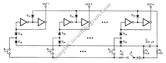
If the button B1 is pressed, the OUT1 will be set high. The OUT1 is also latched by the positive pulse trough resistor diode D1B. OUT1’s pair of converters is locked in this HIGH state by feedback. Beside that, the pulse also pass through diode D1A to the differentiator. The differentiator is formed by R2 and C. This differentiator shorten the pulse. The shortened pulse will reset all the latches, except the latch that has the longer pulse. If the button that is pressed more than one, the output that is latched also more than one at once. [Circuit’s schematic diagram source: seekic.com]