555 IC LED Flasher for Up To 10 LEDs
This LED flasher circuit uses 555 IC, and is capable of driving up to 10 LEDs. The good news is, the use of multiple LEDs in series doesn’t increase the power consumption when compared with using only two LEDs. If we use only two LEDs, then we have to sink the power into a current limiter resistor, which dissipate the power into heat. With the use of 10 LEDs, now almost all the power will be converted into light by this flasher circuit, and only small portion will be dissipated through current limiter resistor. Here is the schematic diagram of the circuit:
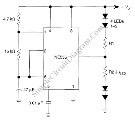 The flashing frequency is determined by 47uF capacitor, as well 4.7k and 15k resistors. To modify the flashing rate, you can change the values of these capacitor and resistors but you should keep the 4.7k resistor replacement above 1k to avoid 555 IC get damaged when pin 7 is internally shorted to ground at the discharging cycle. Please also note that the timing of two alternating LEDs is not symmetric. You can see that the charging time of the 47uF capacitor is determined by the two resistors (4.7k + 15k), but the discharging is determined only by the 15k resistor. To approach the symmetric timing for both group of flashing LEDs, if you want to change the resistor values, then you must keep the 4.7k resistor small eanough compared to the 15k one. The resitors R1 and R2 is determined by the supply voltage and the number of LEDs in each group.Use the following formula:
R=[Supply_voltage – (LED_voltage * NumberOfLEDs)] /LED_current
For example, if we use a 13.6V supply voltage, with 5 red LEDs (LED_voltage = 2V) for the upper LED group, and we want to operate the LED at 15 mA), then we should compute the value of R1 as:
R1 = [13.6V-(2V *5)]/0.015A)
R1= 3.6 V/0.015 A = 240 Ω
[Circuit’s schematic diagram source: seekic.com]