Infrared (IR) Proximity Detector
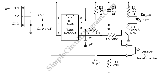
This is infrared (IR) proximity detector circuit. A matched infrared emitter and detector pair is used in this circuit. The voltage controlled oscillator section of the LM567 tone detector IC is used to set the emitter LED pulses at frequency. In this circuit, the center frequency of the VCO is set to about 909 Hz by combination of capacitor C1 and Resistor R1. Here is the circuit:
 A signal is generated for the tone detector IC as the response to the detected reflected light from the emitter. The input frequency is compared with the generated frequency by the decoder. If the frequency is far, R3, 10K pull up resistor, holds it to 5 Volts. If the frequency is close enough, the pin 8 is sent to LOW (ground). An amplifying transistor can be added for higher currents as needed. [Circuit’s schematic diagram source: mondotronics.com]