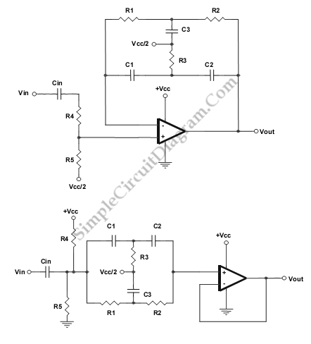
Single Op-Amp Twin-T Band-Pass and Notch Filter
This is a Single Op-Amp Twin-T Band-Pass and Notch Filter circuit. This circuit uses the twin-T topology which requires one or two op amps and three resistors and three capacitors. That’s mean this topology based on a passive (RC) topology. It is not difficult to match the six passive components, but it is critical. we can use single value of capacitance and a single value of resistance to create C3 and R3. Here is the schematic diagram of the circuit:

The component values are determined by following equation:
Bandpass configuration:
C1 = C2 = C
R1 = R2 = R
R3 = R/2
C3 = 2C
Fo=1/(2pRC)
R4 and R5 are used to control gain with R4>100*R5
Notch configuration:
R1 = R2 = R
C1 = C2 = C
R3 = R/2
C3 = 2C
Fo = 1/(2pRC)
R4=R5:HIGH
If the components are matched too closely, the bandpass circuit will oscillate. Selecting the resistor to virtual ground to be one E-96 1% resistor value off will de-tune the bandpass circuit slightly. [Source: Texas Instruments Application Note]