6 Band Graphic Equalizer
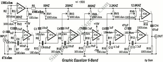
The circuit diagram below shows a circuit of graphic equalizer 6 band of regulation. The potentiometer RV1-6 regulates each band, and the sliding type is the recommended for better visual indication. . The gain is null (flat) in the center position of potentiometer, but in the maximum and minimum position has +/- 15 dB, boost or cutting off, respectively. It […]

Read more
The Full-Wave Rectifier and Averaging Filter

The heart of an average reading, rms calibrated AC voltmeter is shown in figure below. It’s a rectifier and averaging filter. We can remove the averaging function and provide a precision full-wave rectifier by deleting C2 and provide an absolute value generator by deleting C1. By following the signal path for negative and then for positive input, circuit operation may […]

Read more

Digitizing a LVDT Transducer Interface Output

Digitizing transducer interface output voltage is shown on circuit diagram below. The transducer in this case is the NE5521, an LVDT (Linear Variable Differential Transformer) Signal Conditioner. To ensure that the input to the A/D does not go excessively beyond the supply voltage of the A/D, this device is use the diode at the A/D input. For a better description […]

Read more
1 14 15 16 17 18 28