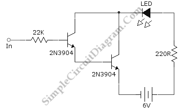
Darlington Transistor Pair Logic Probe
Ideally, any testing equipment will not draw any current from the device under test. This ideal condition can be approximated by designing a testing device with a very high input impedance for negligible loading, and this Darlington logic probe circuit could be one of this. This circuit uses two transistor in Darlington configuration. The connection of transistor will give very high input impedance, so it should draw only very small current from the logic circuit being tested. When there is logic 1 at the input the LED will flash. Here is the schematic diagram of the circuit:
