VOX (Voice-Operated Switch)
This schematic diagram below show a circuit of VOX Box (voice-operated switch). This circuit consist of a Schmitt trigger, a relay driver, and microphone preamplifier. The microphone preamplifier(U1) receive input signal which will be amplified. THRESHOLD control (R8) is fed by the amplified signal. The trigger’s output goes high when the preselected threshold voltage level is exceeded. Here is the schematic diagram of the circuit:
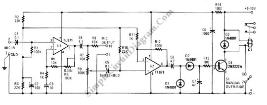
The relay energizer transistor (Q1) is turned on by the signal from U2 which is rectified and the voltage developed across C7. This circuit can be added to control external ac or dc circuit. The external device can be controlled by the relay, and we can select whether this circuit will activate or deactivate the external device when there is a voice by selecting proper terminal on the relay. [circuit’s schematic diagram source: seekic.com]