General Infrared Remote Controlled Relay
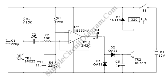
This relay circuit is controlled by almost any type of infrared remote controller. This circuit works on assumption that almost all remote controller use high frequency modulated infrared light. By filtering out un-modulated or low frequency modulated signal, this circuit will be able to remove any interference from ambient infrared light coming from other sources such as sun light, soldering iron, or incandescent lamps. Here is the schematic diagram of the circuit:

This circuit employs a phototransistor which is configured in common emitter amplifier. The C2 does the filtering out of the unmodulated or low frequency signals. The negative-feedback network is formed by R5 an R2. This negative-feedback network set the closed-loop voltage gain of IC1 at 220 times. The amplified output signal from IC1 pin 6 is fed to a half-rectifier-voltage double circuit (D2, C5 and D1). Since the germanium diode has lower forward voltage drop, the germanim diode is used rather than silicon diode. It increases the sentivity of this circuit. The relay RLA coil is controlled by a simple common-emitter switch which is formed by TR2 and C2.