Averager and Peak Hold/Extender Signal Conditioner
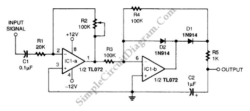
A signal averager circuit can be formed by an amplifier and active signal rectifier, which is implemented using two operational amplifiers in this circuit. The first op-amp is configured as inverting amplifier and the second forms an active half-wave rectifier. The half cycle signal is then filtered by an RC (resistor-capacitor) filter to get the average value. The gain of inverting amplifier can be adjusted up to 5. The circuit gain is set by Adjustable feedback resistor R2. This circuit is not solely an averager, but it also serve the function of peak-hold, especially when there is a brief peaks. Since C2 can be quickly charged through 1k R5, it can follow a quick signal, but then it must slowly discharge through 100k R4 since the back path toward the output IC1-b is blocked by D1. It produce an effect that peaks is displayed over a longer period of time. For slow amplitude-changing signal, this circuit can follow the average amplitude, and for fast amplitude changing then this circuit extend the peak reading by slower decay. This effect if useful for monitoring, for example, an audio channel using a bar graph LED array display. Here is the schematic diagram of this circuit:
