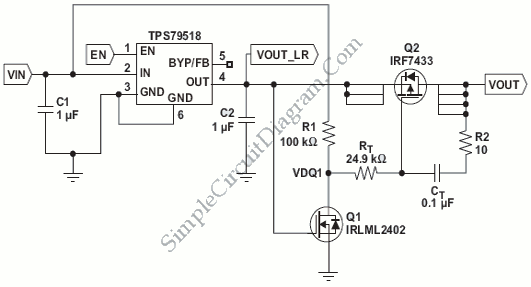
PMOS FET Following The Output for Soft-Start Mechanism
Using the following PMOS FET switch regulator output, in series with the regulator’s load as shown in the picture below is the most simple method. Switch placement should really be noted. To ensure that the regulator remains stable, the switch should be placed after regulators required minimum output capacitance (ie, C3). After regulators suddenly lit, FET Q1 operates as a crude supervisors and pulled low RT. Capacitor CT, effective replace the gate-to-drain capacitance of the FET, and then cause the switch to function as an integrator and provides a more linear transition from the selection voltage components.

The selection component values should be highly considered because they have to meet the following requirements:
1.Q1 and Q2 must have a limit lower voltage than the desired output voltage (Vout > VTH1)
2.Q2’s rDS(on) must be small enough to make drop voltage not too high when the load draw high current
CT was chosen to be much larger than gate-to-drain capacitance (ie, CT>> CGD = Crss). RT selected according to the equation:
RT= (Vout-Vth)/(Ct*(Vout/tRise))
tRise: increase in the desired time (here 5ms)
V ^: Q2’s threshold voltage (0.9 V)
R1 is a pull-up resistor that has a large value
R2 should be chosen to be far smaller than RT.
[Source: Texas Instruments Application Notes]