Power Control: Synchronization by The Mains Voltage
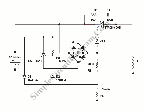
On the circuit diagram below show us a schematic of step-down circuit which is used to approximately divide by two the rms voltage between the line input and the inductive load (L1). C2 and R3 give a turn-on delay of approximately 7 ms.
The diode bridge, with diodes D1 and D2 and R2 resistors have a function to discharge C2 at each line zero voltage. This will maintain the same turn-on delay and reset the voltage charge at each new half line cycle.
The power dissipation is reduced by the transil through R3. Here’s the circuit diagram:

Note: Transil is a transient voltage suppression (TVS) diode, an electronic component used to protect sensitive electronics from voltage spikes induced on connected wires. Transil is trademark of STMicroelectronics. [Source: STMicroelectronics Application Note]